Lubrication
systems and equipment
Mist lubrication is a lubrication system in which the energy of compressed air, typically dry compressed air taken from the plant's air supply, is used to atomize oil, which is transported by air within a low-pressure distribution system to multiple lubricant application points.
Types of mist
Near the lubricant application points, the pipes come down from the general distribution, which end in a collector-distributor in which some devices called recondensers are installed and they act as restriction orifices in which, due to the induced turbulence and/or due to the turbulence caused by the movement of the element, the oil particles join together to produce larger particles capable of "soaking" and lubricating the moving surfaces of the system.
The mist contains oil particles with a diameter of 1.0-2.0 μ, in a proportion of 1 oil particle per 200,000 air particles. This mixture is not a volatile organic compound, so there is no risk of explosion or combustion. In practice there are two methods to apply lubricating oil mist: pure mist and maintenance mist (or preservation mist). The type of equipment and its operating conditions determine the way of application. Given its advantages, it is recommended to use pure mist, whenever possible, to lubricate rotating equipment.
Pure oil mist lubrication
The Mist lubrication method has unique advantages. The low level of lubricant application made possible with oil mist provides continuous lubrication without the need to design a recirculation system. This reduces the manufacturing and installation cost of many designs and improves maintenance by reducing oil consumption, particularly where gasket maintenance is a problem. Heat generation due to lubricant friction is minimized in applications where a liquid oil tank is no longer available. We call this pure mist, or dry oil mist delivery mode, to differentiate it from wet oil tank applications where mist is used tu purge the bearing housing. The main characteristic of this form of mist application is that the oil level inside the equipment's bearings and the lubricating ring are eliminated. In this case, lubrication is provided entirely by the recondensed oil mist, which enters the housing and passes through the bearings. The mist condensed in the housing will drain into a collection cup connected to the bottom of the equipment.
Pure mist is mainly applied to equipment that has rotating element bearings, such as centrifugal pumps and electric motors. The only exceptions are those applications in equipment with chocks or sleeve bearings where the application of maintenance mist is preferable to ensure the formation of an adequate lubricant film on the oil level.
Components
Console:
Generally, a mist lubrication system is made up of a console in which:
– The mist is generated.
– The operating values of all variables are monitored.
– An oil supply tank or reserve is provided.
– Distribution lines that transport the mist to the points to be lubricated.
– Distribution pipes that divide and direct the mist to each application.
– Recondensers that control the flow and type of mist for each point to be lubricated.
– Vents that discharge clean air into the environment, through centrifugal systems.
– Drainage lines to collectors.
These systems can vary in complexity according to the type and number of points to be lubricated.
The mist generating console includes the necessary instrumentation to monitor the mist generation variables. The main mist generating unit is independent of the auxiliary generating unit and they are activated by separate controls. Ten process variables are monitored in the main generating head. If any of the variables exceed a predetermined upper limit or are less than a lower limit, a fault signal (alarm) pops up on the control panel. The operating variables that are monitored, as well as the measuring instrument used, are presented below:
- Air inlet pressure to the console: pressure transducer, 4-20 mA output.
- Regulation of the air inlet pressure in the main generating head: pressure transducer, 4-20 mA output.
- Air temperature: 2 type K thermocouples.
- Oil supply pressure: pressure transducer, 4-20 mA output.
- Oil level in the tank: level transmitter.
- Oil temperature in the tank: 1 type K thermocouple.
- Generated mist pressure: two-wire pressure transducer, 4-20 mA output.
- Generated mist density: density detector/transmitter, 4-20 mA output.
- Low oil level in the reserve: level switch.
- Ambient temperature: platinum RTD sensor, 100 Ω.
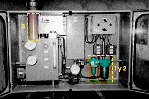
Base components:
- Air line separator filter, which ensures clean air distribution to the generator.
- Air pressure reducer, which controls the air flow to the generator.
- Generator provided with Venturi/Vortex nozzle with regulation screw, air suction tube and oil tank with optical level indicator.
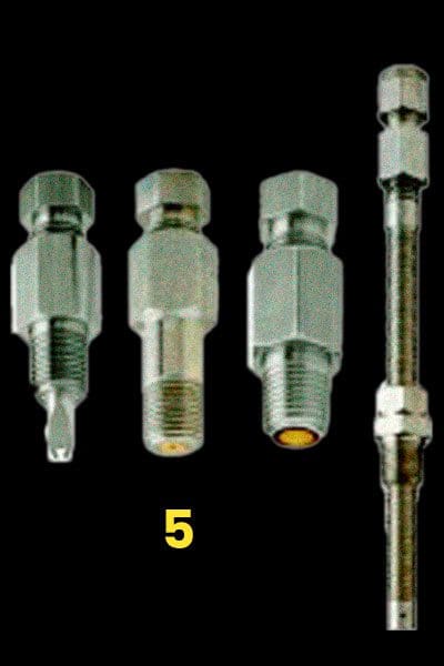
- Mist distribution pipe set for connection to the application fittings.
- Mist application, spraying or recondensation fittings to dose or convert the Mist at each lubrication point.
Accessory components:
- A solenoid valve to open and close the airflow to the generator.
- An oil heater, to maintain the oil in the generator's tank at the appropriate viscosity for good Mist generation.
- An air heater that, regardless of variations in ambient temperature, maintains the oil/air ratio constant and allows high viscosity oils to be atomized.
- A level with electrical contact for signaling the minimum level and automatic tank filling.
- A device provided with an electrical contact or transmitter to control the delivery pressure, high or low.
- A pressure gauge indicating the Mist delivery pressure.